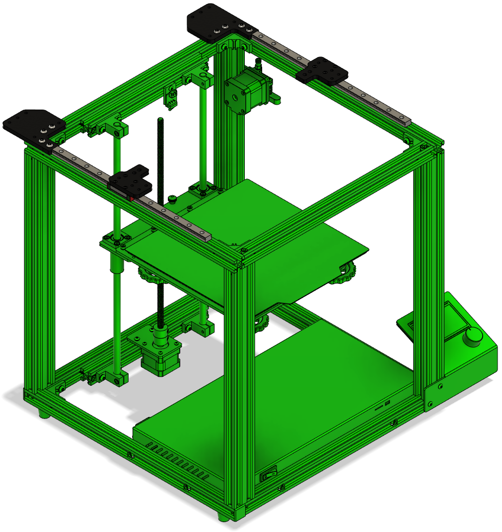
ENDER 5 COREXY INSTALL GUIDE
There are (2) printed tools that will need to be printed to aid in assembly please see the downloads below before install.
Step:1
Remove all stock components from the frame so the frame has nothing mounted to the top extrusions.

Step:2
Install motor mount lower brackets using M5x12BHCS and M5 Tnuts.
Please note: most printers only (6) bolts will secure the plates the other 2 bolts are to be left out as the frame bolts interfere.

Step:3
Install (2) linear rails with M3x8SHCS and M3 Tnuts using the rail centering tool.
Rail Centering Tool .STL

Step:4
Install lower Y mounts right & left with M3x6SHCS.
Step:5
Install Y axis extrusion with M5x12BHCS and M5 Tnuts. (insure smooth movement on rails adjustment may be required.)

Step:6
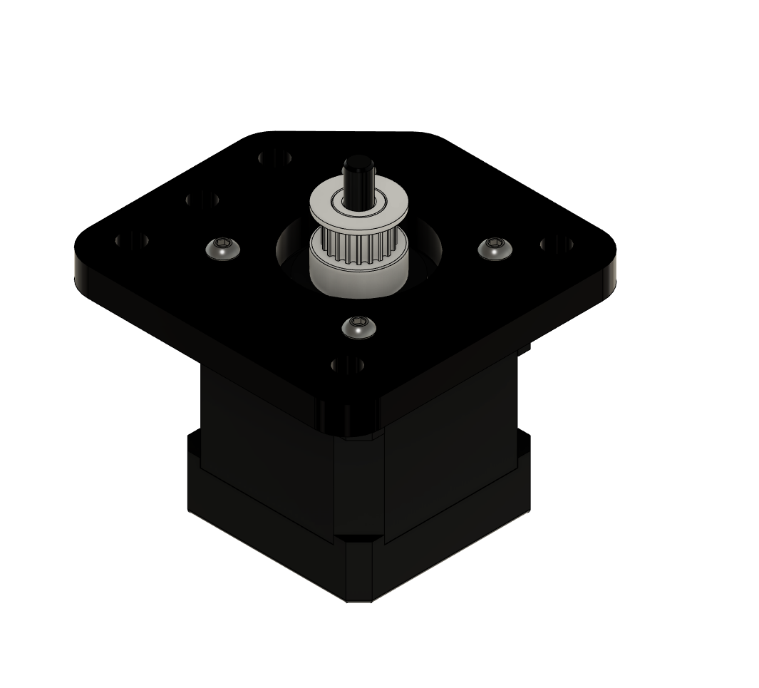
Mount drive gears to the steppers using the drive gear spacer tool (right side). then attach the motor to the upper motor mount as shown using M3x10BHCS
Drive Gear Spacer Tool .STL
Step:7
Mount drive gears to the steppers using the drive gear spacer tool (left side). then attach the motor to the upper motor mount as shown using M3x10BHCS

Step:8
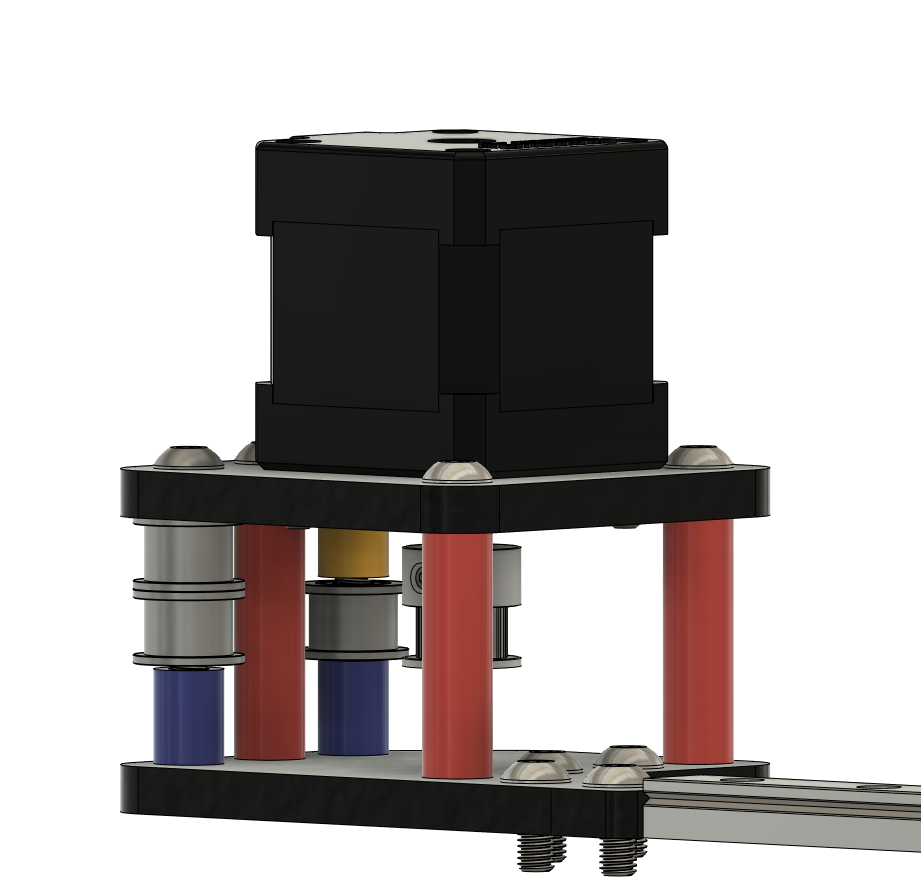
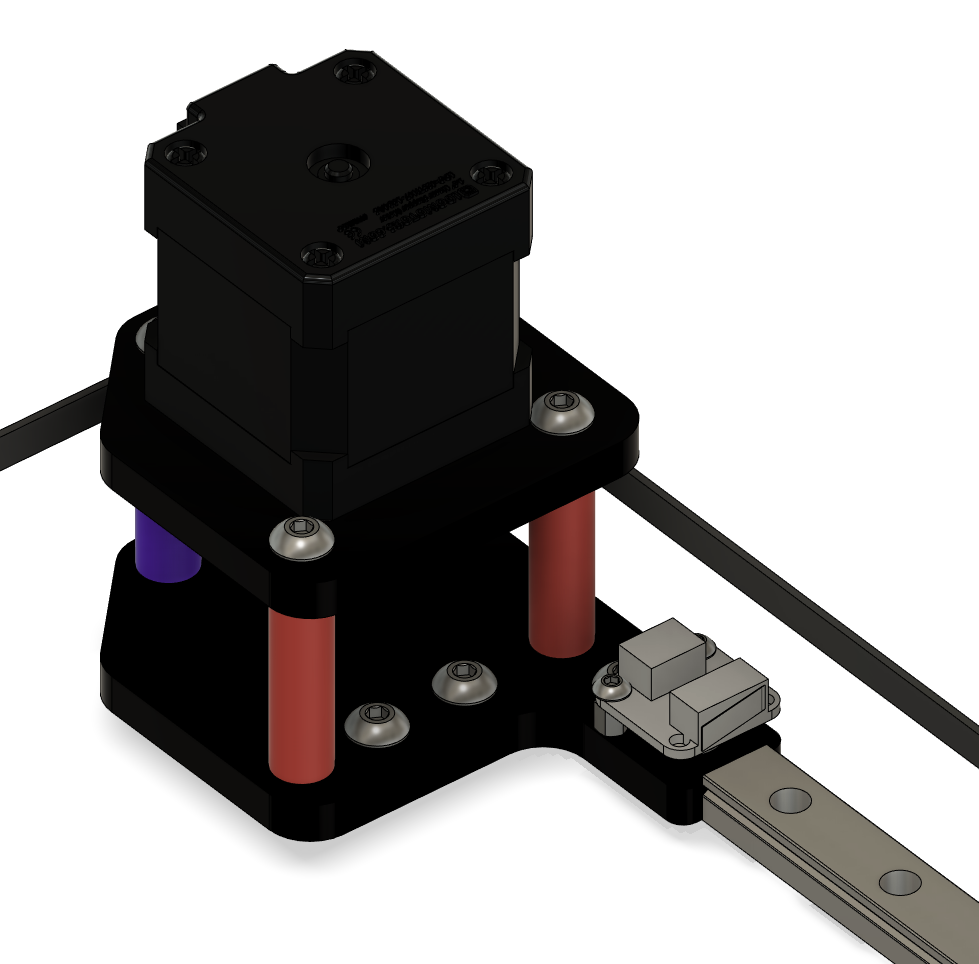
Install the right motor assembly using M5x45BHCS and red spacers. Then install the smooth pulleys and purple and blue spacers as shown below.

Step:9
Install the left motor assembly using M5x45BHCS and red spacers. Then install the smooth pulleys and blue and yellow spacers as shown below.
Step:10
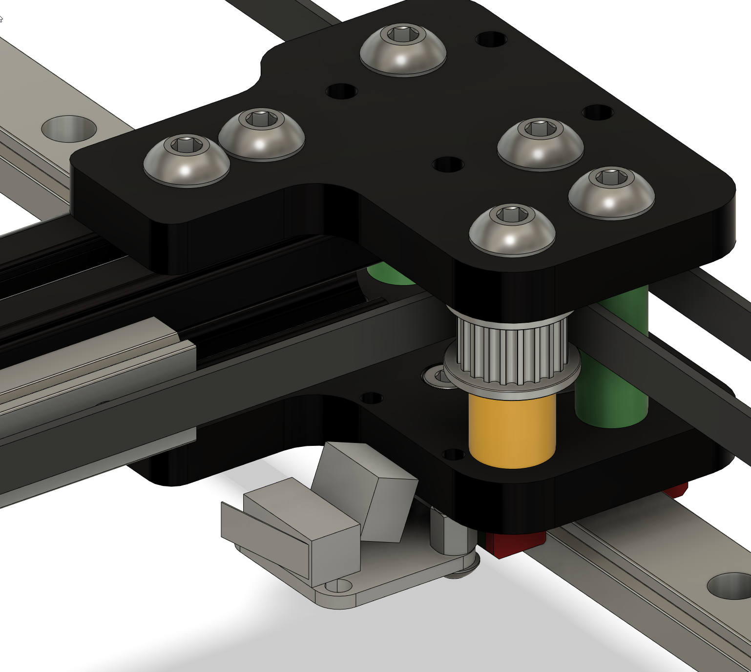
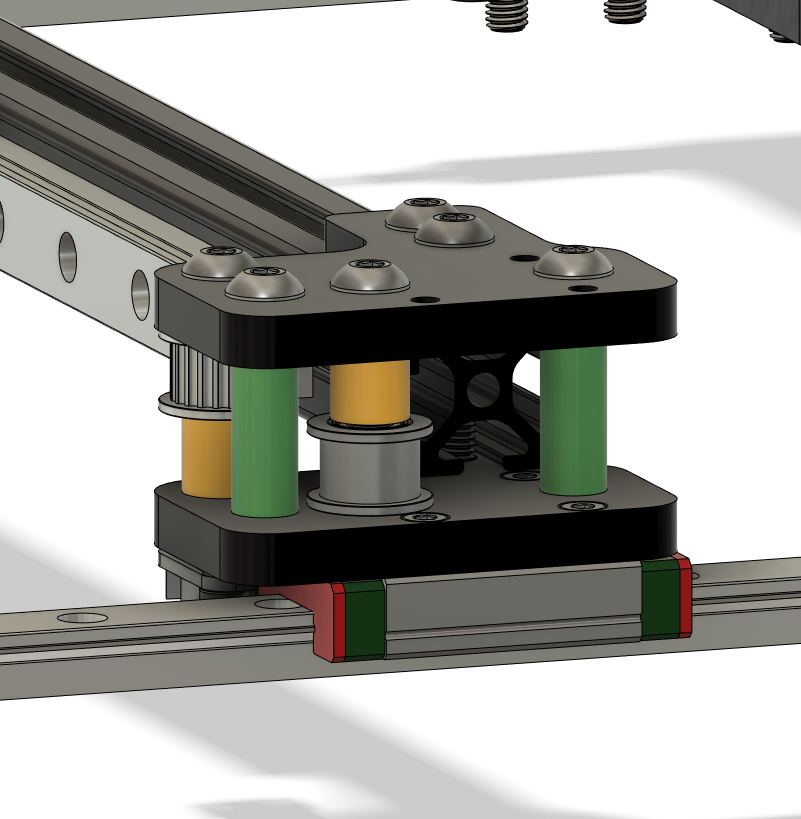
Install the upper Y mount (left) using M5x30BHCS with green spacers and attach to the extrusion using M5x12BHCS and M5 Tnuts. Then install the pulleys and yellow spacers as shown below.

Step:11
Install the Upper Y Mount (Right) using M5x30BHCS with green spacers and attach to the extrusion using M5x12BHCS and M5 Tnuts. Then install the pulleys and yellow spacers as shown below.
Step:12
Install the linear rail to the extrusion using M3x8SHCS and M3 Tnuts center the rail on the extrusion left - right. Use the rail centering tool to center rail top - bottom.

Step:13
Install X carriage using M3x8SHCS. Install standoffs as shown below.

Step:14
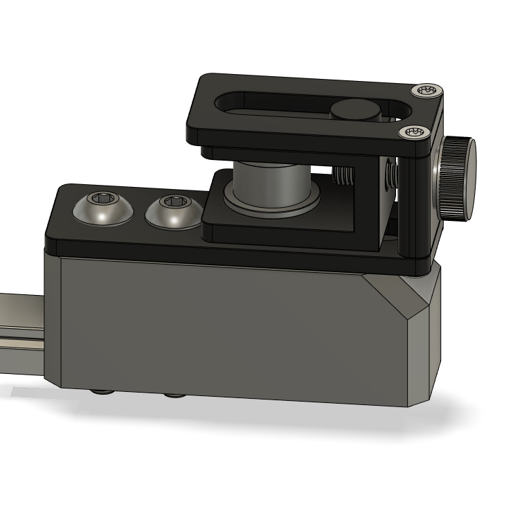
Build left tensioner assembly - the printed part needs (2) orange spacers pressed in the holes. Install the left tensioner assembly the assembly mounts to the frame tight against the rail using M4x20BHCS and M4 Tnuts.

Step:15
Build right tensioner assembly - the printed part needs (2) purple spacers pressed in the holes. Install the left tensioner assembly the assembly mounts to the frame tight against the rail using M4x30BHCS and M4 Tnuts.
Step:16
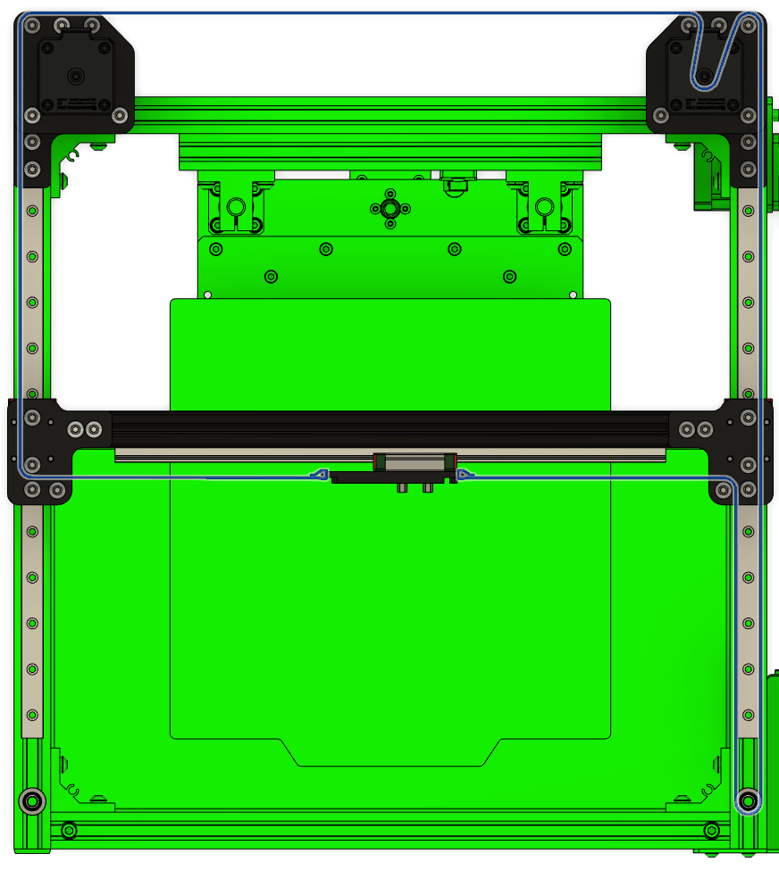
Install lower belt following the routing below secure at X carriage with 2 zip ties. (during install make sure tensioner is all the way loose)

Step:17
Install upper belt following the routing below secure at X carriage with 2 zip ties. (during install make sure tensioner is all the way loose)
Step:18
Install limit for Y using stand offs and M3x4BHCS
Step:19
Install limit for X using stand offs and M3x4BHCS (limit plug will need to be bent upward to be able to plug in)